Background introduction
There are many types of portable battery-powered medical devices , and there are many options for charger control circuits that can reliably power these devices. For example, passive component tantalum capacitors (such as chip tantalum capacitors and chip capacitors) can improve the overall performance of the charger control and energy storage system in portable devices. Portable battery-powered medical devices can be powered either from a disposable battery or from a rechargeable battery that is charged with a battery charger. The need for portability and ease of use of medical devices has led to numerous improvements in charge control circuits. Chargers and battery systems have evolved from circuits consisting of many components to integrated microprocessor-based systems that use fewer passive components and less board space.
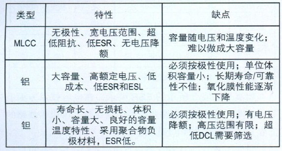
In view of the high reliability requirements of medical devices, this paper gives examples of the design and trade-offs of commercial tantalum capacitors and medical tantalum capacitors, and introduces some new developments that help improve performance. This article also highlights the general selection criteria for capacitive technology and the progress of packaging technologies that can be used in portable medical devices. The most commonly used types of bulk capacitors in portable medical devices are multilayer ceramic capacitors (MLCC), aluminum electrolytic capacitors, and solid tantalum capacitors. Table 1 describes some of the general characteristics and possible shortcomings of each capacitor technology.
Table 1 Types of bulk capacitors used in portable medical devices
Battery charger basics
For portable devices that use rechargeable secondary batteries, many types of chargers can be used: a buck charger, an offline charger, or a linear regulator/charger. The most common type is the buck charger. This charger converts the battery source voltage to a lower voltage and regulates it. The converter can be powered by an external AC/DC adapter or an internal adapter circuit. The linear regulator is compact and ideal for low-capacity battery charger applications. The single-chip integrated solution powers portable devices while charging the battery separately.
Figure 1 shows an example of a small DC/DC switching regulator. It provides a synchronous pulse switch for the battery charger. The pulsed battery charging system has low heat dissipation and is available in a TSSOP package with a height of only 1.2 mm. The device is feature rich, including the ability to isolate the battery (Vbat) from external power supplies during shutdown.
There are many types of capacitors used in the charger. Input decoupling capacitors are used to bypass the noise. A 0.1μF MLCC capacitor is typically placed near the Vcc pin to filter out high frequency noise.
Figure 1 Lithium-Ion or Ni-Cd/NiMH microprocessor battery charger using Vishay Siliconix Si9731
The choice of output capacitor type should depend on the appropriate ESR to meet the stable load line range and should be evaluated for the following items:
1. Can reduce power consumption
2. Can reduce the ripple voltage
3. Can meet the requirements of the system load line.
The converter is responsible for providing the load current and voltage. As the load changes, the current increases and the voltage drops. The regulator can maintain a constant voltage, but does not respond quickly to changes in load current, so use large capacitors to cope with such changes and prevent voltage drops. If the current output from the converter is to pass through the inductor, it will not respond instantaneously. In this case, a parallel capacitor bank is connected across the load to pull up the voltage. Sometimes MLCC and tantalum capacitors are mixed to reduce the ESR of the overall bulk capacitor. Since the impedance of the MLCC is low, it will be charged first, then the bulk tantalum capacitor.
Power and output capacitor requirements
The battery used in portable medical devices is either a disposable battery or a secondary battery. Disposable batteries are generally only used once. Active chemicals are depleted during the operation of the circuit. Once the discharge is complete, the circuit will stop working and a new battery must be replaced. The secondary battery can be charged after the discharge is completed because the chemical reaction that generates the electrical energy can be reversed, thereby realizing charging of the battery system. The choice of power source and battery type depends on the application. The disposable battery types commonly used in medical equipment are alkaline batteries and lithium batteries.
Secondary batteries include lithium batteries, nickel-cadmium batteries (NiCad), nickel-hydrogen (NiMH) batteries, and lead-acid batteries. Among them, lithium batteries are most commonly used because lithium batteries have the largest volumetric energy density and mass energy density, and the discharge rate is extremely low, which means that there is good charge retention ability when idle.
Table 2 Power consumption and capacity range of tantalum capacitor
Portable device circuits require an output capacitor, which is typically powered by a single or secondary battery that mitigates voltage overshoot or undershoot during load transients. To effectively filter out noise, the equivalent series resistance (ESR) of the capacitor is a key consideration. The output capacitor is used to handle the ripple current and voltage of the circuit. The overheating of the capacitor bank needs to be controlled so that the maximum allowable power dissipation is not exceeded during circuit operation. It is necessary to determine that the ripple current through the output capacitor does not exceed the allowable value.
Table 2 summarizes the maximum allowable power ratings for various packages (divided by case size) at +25 ° C and f = 100 kHz. For applications where the temperature rise is above +25 °C, further derating is recommended. Please refer to the capacitor manufacturer's recommendations for power derating for applicable tantalum packages.
The maximum allowable AC ripple current (Irms) can be calculated using the formula P=Irms2 x ESR, where P is the maximum allowable power corresponding to the tantalum capacitor case size, and ESR can be calculated based on the operating frequency of the capacitor.
For tantalum capacitors, the appropriate voltage derating specification must also be followed and must not exceed the manufacturer's recommended rating. The operating voltage of the output capacitor should be determined by the state of the voltage circuit. It can be calculated according to the formula Vrated=Vpeak+Vdc, that is, the ripple voltage plus DC voltage noise. The allowable ripple voltage is calculated as E = IxZ, where Z represents the capacitor resistance. Overall, a lower ESR can help reduce output ripple noise.
Adding a large-capacity capacitor to the circuit also enables power-up under no-load conditions (when the battery is not operating, using line current). When using line current supply, the derating specification should be followed when selecting the rating of the large capacity tantalum capacitor.
Nursing pad is a disposable sanitary product made of PE film, non-woven fabric, fluff pulp, polymer and other materials.
Adult nursing pads are mainly used for people who have undergone surgery, those who are paralyzed, and those who cannot take care of themselves. The adult nursing pad is easy to replace, which can ensure that the mattress under the building will not be soiled.
Cloth Underpads,Absorbent Underpads,Protective Underpads,Washable Underpads For Adults
Shandong Kangshun Daily Products Co., Ltd , https://www.centurybenifit.com